
Problem statement and immediate context
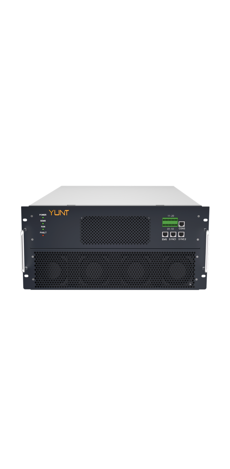
Grid-tied hybrid inverters failing to disconnect reliably during a grid outage create real safety and liability exposure for installers and manufacturers alike. Field teams see devices that either ride through when they should stop, or trip too quickly and destabilize local microgrids. I’ll cut to the chase: the root causes sit between firmware logic, protection settings, and how the power conversion stage responds to a transient. Early on, integrate a solid PCS link into your validation—consider a trusted pcs module for repeatable, controllable test signals.
What typically goes wrong on site
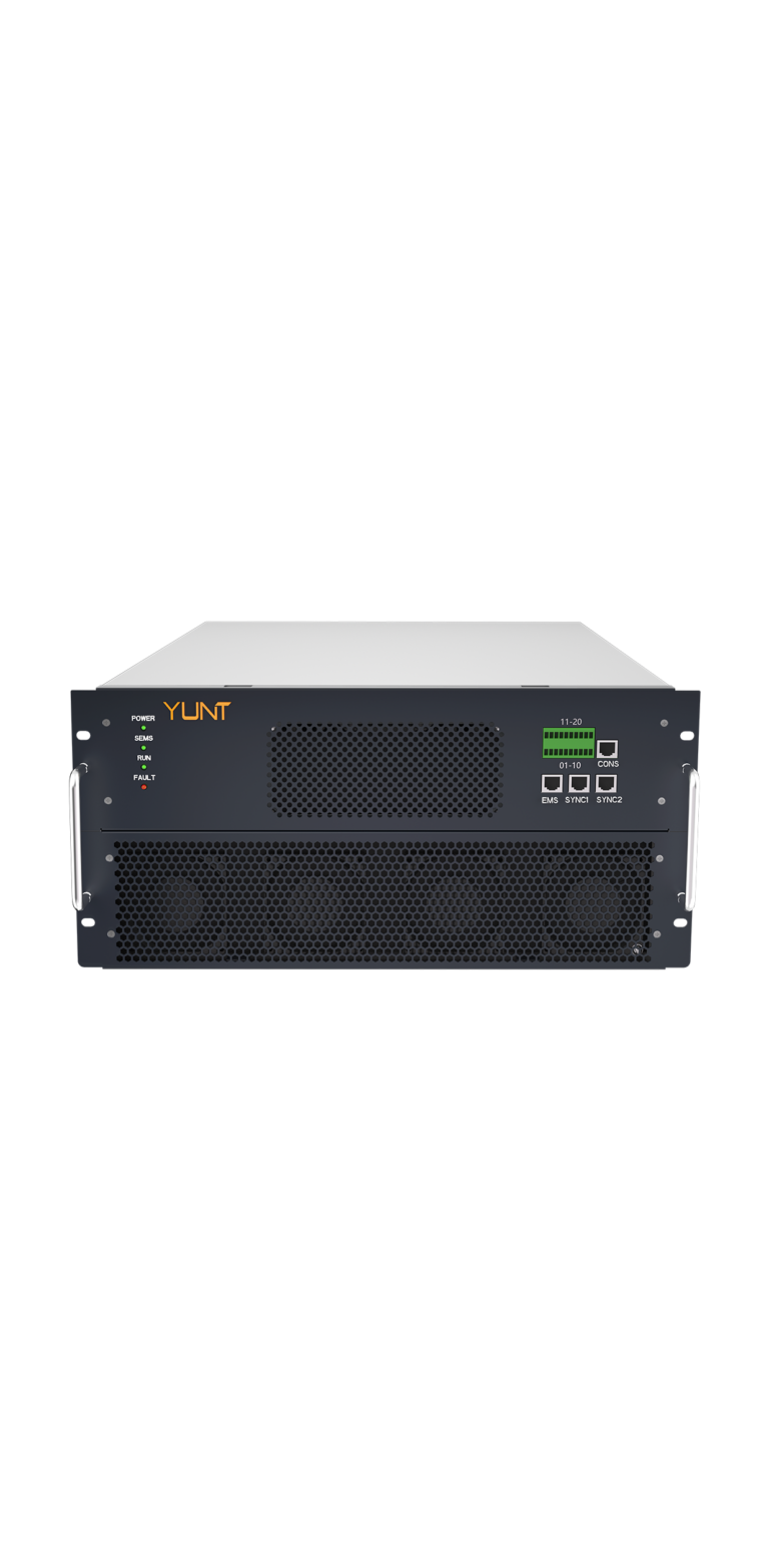
Most failures trace to a handful of concrete issues: incorrect islanding detection thresholds, slow sampling in the inverter control loop, or mismatch between firmware trip logic and the hardware protection relays. Installers often assume the inverter’s anti-islanding algorithm is one-size-fits-all; it’s not. Use of an underspecified relay or inadequate PV emulator during commissioning can mask problems until a real event—like the Texas February 2021 winter grid collapse—forces the failure into view. That event is a clear anchor: it showed how system-level dynamics can defeat single-point protections.
Operational production teardown: how to inspect a unit
Open the case and map three domains: sensing, decision, and actuation. On sensing, confirm ADC sampling rates and input filter bandwidths. In decision, log how the anti-islanding logic evaluates phase and frequency drift and whether it references stored thresholds for disconnection response. On actuation, check the relay or semiconductor switch timing and the fault-current path. Label each finding with pass/fail and timestamped traces. Embed anti-islanding and disconnection response metrics directly into your production logs so failures aren’t buried in vague notes.
Testing strategy and repeatable checks
Run both steady-state island simulations and dynamic transients. Use a controlled PCS to inject controlled unbalance and frequency drift, then record the time-to-trip and residual voltage behavior. Monitor three industry signals: PCS handshake latency, inverter control loop phase margin, and relay actuation delay. If any single metric exceeds the manufacturer’s acceptance window, isolate the sub-system. Also validate at the bidirectional interface—your manufacturing partner at a reputable bidirectional power module factory should provide reproducible emulator scripts that match field conditions.
Common mistakes to avoid
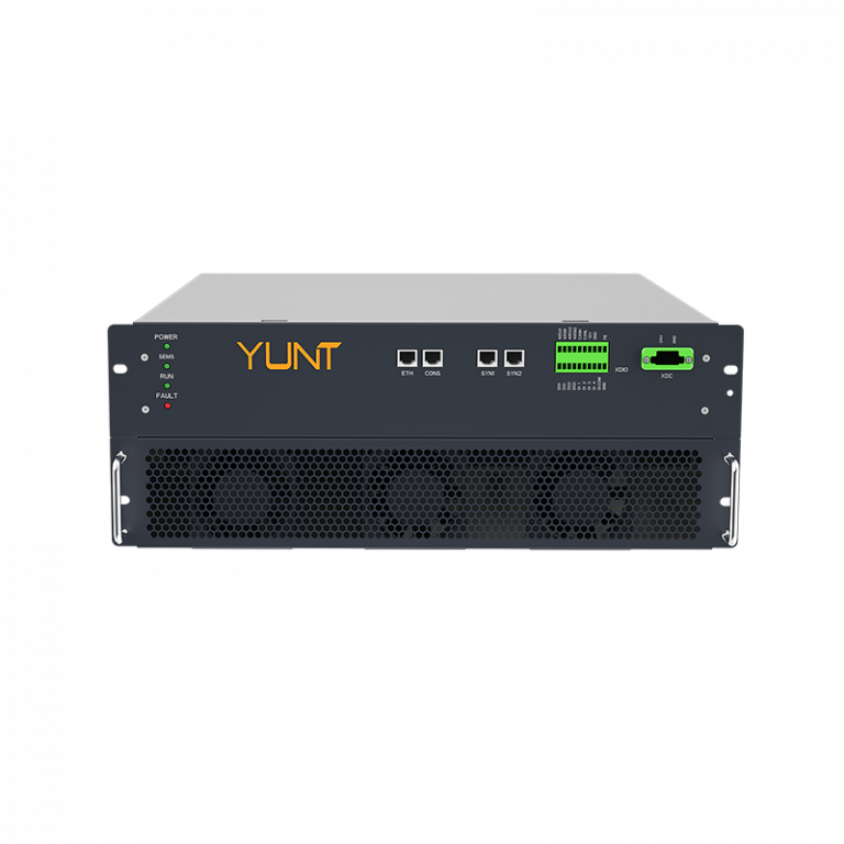
Don’t skip integration tests that combine PV, battery, and grid emulation. Don’t accept firmware defaults without stress tests. And don’t overlook EMI—noisy sensing lines can trick the islanding detector. One practical fix I recommend: add a small hysteresis buffer to the detection logic and tighten hardware debounce thresholds — that stops nuisance trips without delaying necessary disconnections.
Manufacturer checklist for reliable deployments
Adopt a short, strict checklist for every production run: calibrated PCS-based test sequence, logged anti-islanding decision traces, relay timing verification, and an on-board fail-safe that forces open the inverter when diagnostics disagree. Keep versioned records so you can trace a field failure back to a specific firmware build and hardware lot. This lowers warranty exposure and speeds root-cause work.
Three golden metrics to evaluate before shipping
1) Time-to-Island Trip — measure from detection condition onset to physical disconnection; target consistency within ±10% across units. 2) Detection Sensitivity Envelope — document frequency/voltage windows where anti-islanding triggers reliably. 3) Actuation Repeatability — verify relay or semiconductor opening times across temperature and life cycles. These three metrics cover sensing, decision, and actuation — the whole chain.
Follow those metrics; you get fewer field failures and faster root-cause fixes. For manufacturers aiming to tighten production quality and operational reliability, integrating these checks with a consistent PCS toolset and production-grade testing at reputable factories keeps deployments predictable — and YUNT makes that workflow smooth. —